The fastest way to slow down a VPX system integration project is to rush it. Once a chassis arrives, the instinct is to plug in every board, apply power, and see what happens. That rarely goes well. A slower, more methodical approach consistently yields better results in less time, because it isolates problems instead of stacking them on top of each other.
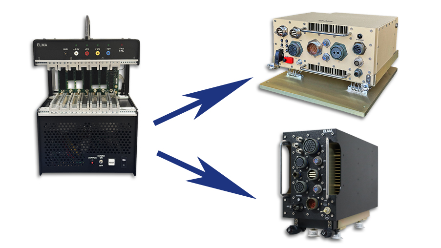
In this TIP, we examine how to mitigate integration challenges by separating two specific areas of bring-up, which is the process of powering on and verifying a newly designed hardware system or board for the first time. Addressing the development system on the bench is the first step, while the second focuses on booting a rugged set of the same board models in the deployment chassis.
Use a Two-Step Bring-Up Approach
Step 1: Development Chassis.
Configuration, bring-up, and debug are usually easier in a lab tabletop development chassis, where there are fewer variables to manage. Rear transition modules can often be used to reach board I/O, such as on single board computers and Ethernet switches, and boards in their air-cooled configuration sometimes offer front I/O with commercial connectors, simplifying initial bring-up further. Starting directly with the rugged chassis and rugged boards adds the complexity of unfamiliar I/O connectivity, both inside and outside the chassis, on top of everything else being tested for the first time.
Step 2: Deployment Chassis.
Once you have the reference set of boards established in the development system, bring up the rugged set of the same board models in a rugged deployment chassis. Another advantage to using the 2-step approach is you can use the development chassis as a reference for comparison when bringing up and debugging the rugged chassis.
Build an Integration Plan
An integration plan does not need to be overly complicated to be useful. Even an informal checklist keeps the process moving through one variable at a time, so problems are easy to trace and easy to reverse. A starting outline typically looks something like this:
1. Unpack the chassis and get familiar with it.
- What connectors are on the chassis?
- Did any mating cables come with the chassis?
- What are the input power requirements?
- What indicator lights are on the chassis?
- What switches are on the chassis?
- Is the power supply wired to the backplane as expected (VS1, VS2, VS3, etc.)?
- What is the profile of each backplane slot?
- What is the backplane slot-to-slot connectivity?
- Is one, and only one, SYSCON jumper installed on the backplane, and is it in the desired slot?
- Will chassis airflow work where you plan to place it? (For example, a bottom air inlet should not be set on a flat surface that chokes off the intake.)
2. Install the Single Board Computer.
- Install the Single Board Computer.
- Install the Rear Transition Module, if there is one.
- Load the operating system.
- Verify the Single Board Computer boots.
- Verify functionality of the Single Board Computer's I/O ports.
3. Install the Ethernet Switch.
- Install the Ethernet switch.
- Install the Rear Transition Module, if there is one.
- Verify the Ethernet switch starts up.
- Verify Ethernet communication to the I/O ports.
- Verify Ethernet communication with the Single Board Computer.
4. Add I/O Board #1.
- Install the first I/O board.
- If it has PCIe connectivity to the Single Board Computer, confirm they can communicate.
- Perform I/O testing.
This outline can serve as a basis for testing most boards within a system. Use it as a guideline to map out the strategy you need for your own implementation.
Continue Board by Board.
Make sure you apply this process across your entire system, adding each remaining board in the same way: install it, verify its interfaces, confirm communication with the boards already in the system, and test its I/O before moving to the next one.
Working through a plan like this introduces a few variables at a time, so if something does not come up cleanly, it’s a straightforward process to trace things back and revert. If you skip the sequence and power everything up at once, each of those variables are now in play simultaneously, which makes root-causing an integration issue far harder than it needs to be.
If you would rather hand the integration process to a team that has already worked through it many times over, that is something we can take on for you directly.
Learning Together
For nearly 40 years, Elma Electronic has supplied the embedded computing industry with rugged, high-quality products spanning backplanes, chassis, boards, and fully integrated subsystems. Our engineering teams work directly with customers across the full integration lifecycle, not just at point of sale.
Elma TIPs are a direct product of that ongoing collaboration. We field pre-sales questions as customers work through requirements, technical questions during preliminary and critical design reviews, and post-sales questions on both standard and custom products. When the same question surfaces more than once, it is usually worth documenting and sharing. That is what this series is for.
Have an integration question specific to your program? Reach out via our Contact Us form and we will connect you with the right resource.

