Modern VPX systems are smaller, faster, and more signal-dense than ever. That combination puts cabling (once a relatively simple afterthought) squarely in the critical path of system integration. Today's chassis routinely carry high-speed protocols such as USB3,DisplayPort, LVDS, 10 Gigabit Ethernet, RF coax, and fiber optic, each with its own connector, bend radius, and spatial footprint.
As chassis dimensions shrink and board density increases, mechanical cabling decisions made early in the design process can determine whether integration goes smoothly or becomes a costly rework effort. This TIP walks through six common cabling challenges engineers encounter in VPX integration, along with the practical approaches used to address them.
Six Cabling Integration Challenge sand How to Address Them

1.Tight Bend Radius
When chassis depth is limited, cables frequently have little clearance between the connector and the chassis wall or cover. A bend radius that is too tight places mechanical stress on the cable, risking signal degradation or physical damage, particularly in fiber optic runs.
Selecting the appropriate fiber LC boot (the flexible sleeve at the cable-connector junction) is an effective mitigation. Angled or extended boots allow the fiber to exit the connector at a gentler curve, protecting the cable without requiring additional chassis real estate.
2. Limited Spacing for Coax
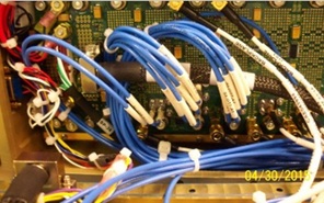
In top-loading chassis configurations, the gap between the rear of the backplane and the chassis bottom can be extremely tight. Standard straight RF connectors often cannot be routed cleanly in this space (Figure 2).
Right-angle RF connectors address this directly: they redirect the cable path parallel to the backplane, preserving clearance while also distributing cable stress across more of the run rather than concentrating it at a single bend point. This approach serves both space and durability goals simultaneously.
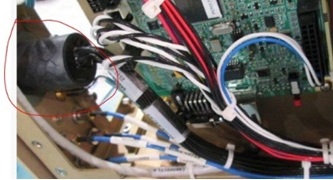
3. High-Profile Backshells
Molded backshells on electrical cables can extend two to three inches beyond the connector body. In dense configurations, a backshell of this size can encroach on adjacent board slots or push the chassis beyond its target envelope if not accounted for early. See figure 3.
Identifying backshell dimensions during the design phase, before hardware is committed, allows engineers to adjust slot assignments, cable routing paths, or chassis depth before they become production constraints.
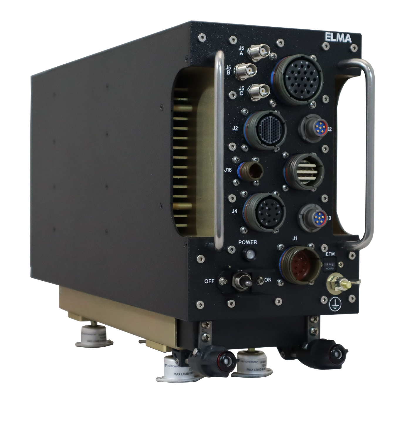
4. I/O Connector Count and Size
In some system architectures, the sheer number and physical size of I/O connectors dictates chassis dimensions rather than the other way around. When connector real estate determines the envelope, it needs to be factored into chassis design from the start, not retrofitted after the fact.
The Elma ATR-3600S provides a useful reference point: its layout was shaped directly by I/O connector requirements in the SOSA® aligned half ATR, demonstrating how connector planning and chassis design must proceed in parallel (figure 4).
5. Cable Harness and System-Level Simulation
Individual cable solutions address point problems, but the most effective way to catch cabling conflicts is to model the full system early. Simulating or prototyping the mechanical design before production, including PCB layout, enclosure structure, cable harness, and all I/O, surfaces interference issues while they are still inexpensive to resolve.
Engineers who have seen the same cabling problems across multiple programs carry an advantage here. Recognizing a recurring conflict pattern before it appears in hardware is one of the more practical forms of design risk reduction.
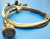
6. External Breakout Cables
One of the more consistently overlooked cabling requirements is external breakout cables: the cables needed to connect the chassis to test equipment, development systems, or mission hardware during integration and debug.
It is not uncommon for a program to specify a fully custom rugged chassis and reach system integration before anyone has defined what external cable harnesses are needed (figure 5). At Elma, we flag this requirement early and can develop custom breakout cables for customers who prefer not to manage that work in-house.
Cabling Is a System-Level Decision
In today's VPX systems, cabling is not a downstream detail; it is a design input. Bend radius, backshell profiles, connector counts, harness routing, and external cable requirements all have mechanical and schedule implications that compound when they surface late.
Accounting for these factors early, alongside the PCB and enclosure design, is one of the most effective ways to reduce integration risk and protect program timelines.
Learning Together
For 40 years, Elma Electronic has supplied the embedded computing industry with rugged, high-quality products spanning backplanes, chassis, boards, and fully integrated subsystems. Our engineering teams work directly with customers across the full integration lifecycle, not just at point of sale.
Elma TIPs are a direct product of that ongoing collaboration. When the same questions and challenges appear across multiple programs, they are worth documenting and sharing. That is what this series is for.
Have a cabling question specific to your program? Reach out via our Contact Us form and we will connect you with the right resource.